How to Replace MSI GE62 GP62 GE72 GP72 WS60 GT62VR GT72VR keyboard
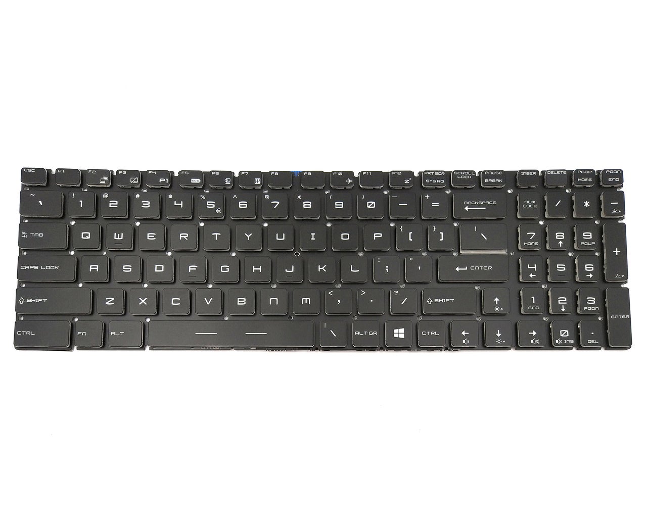
New MSI GE62 GP62 GE72 GP72 WS60 GT62VR GT72VR Gaming Keyboard RGB Backlit US
$49.66
$45.66
Layout: US
Condition: Brand New
Color: Black With Full Colorful Backlit
Warranty: 3 Months
Remark: Please check the images and description carefully. You will receive what you see!
Shipping: Free Shipping
Compatible Keyboard Part#:
V143422AK1
Compatible Laptop model#:
CR62 6ML, CR62 Series,
CR72 6ML, CR72 Series,
CX62 2QD, CX62 6QD, CX62 7QL, CX62 Series,
CX72 7QL, CX72 Series,
GE62 2QD, GE62 2QE, GE62 2QF, GE62 Apache, GE62 Apache Pro, GE62 Series,
GE72 2QD, GE72 2QE, GE72 2QF, GE72 6QC, GE72 6QD, GE72 6QF, GE72 Apache, GE72 Apache Pro, GE72 Series,
GL62 6QC, GL62 6QD, GL62 6QF, GL62 Series,
GL72 6QC, GL72 6QD, GL72 6QF, GL72 Series,
GP62 2QD, GP62 2QE, GP62 6QE, GP62 6QF, GP62 7QF, GP62 7RD, GP62 7RDX, GP62 7RE, GP62 7REX, GP62 Series,
GP62M 7RD, GP62M 7RDX, GP62M 7REX, GP62M Series,
GP62MVR 6RF, GP62MVR 7RF, GP62MVR 7RFX, GP62MVR Series,
GP62VR 7RF, GP62VR Series,
GP72 2QD, GP72 2QE, GP72 6QE, GP72 6QF, GP72 7QF, GP72 7RD, GP72 7RDX, GP72 7RE, GP72 7REX, GP72 Series,
GP72M 7RDX, GP72M 7REX, GP72M Series,
GP72MVR 7RFX, GP72MVR Series,
GP72VR 6RF, GP72VR 7RF, GP72VR 7RFX, GP72VR Series,
GS63VR 6RF, GS63VR 7RF, GS63VR Series,
GS63VR Stealth Pro, GS73VR 6RF, GS73VR 7RF, GS73VR Series, GS73VR Stealth Pro,
GT62VR 6RD, GT62VR 6RE, GT62VR 7RD, GT62VR 7RE, GT62VR Dominator Pro, GT62VR Series,
GT72VR 6RD, GT72VR 6RE, GT72VR 7RD, GT72VR 7RE, GT72VR Dominator Pro, GT72VR Series,
GT73VR 6RE, GT73VR 6RF, GT73VR Series,
PE60 6QD, PE60 6QE, PE60 7RD, PE62 7RD,
PE70 6QD, PE70 6QE, PE70 7RD, PE72 7RD, PE72 7RE,
WE63 8SI, WE63 8SJ, WE65 9TI, WE65 9TJ, WE73 8SJ, WE73 8SK,
WS60 2OJ, WS60 6QI, WS60 6QJ, WS60 Series,
WS63 8SJ, WS63 8SK, WS63 8SL, WS72 6QH, WS72 6QI, WS72 6QJ, WS72 Series,
WT72 2OK, WT72 2OL, WT72 2OM, WT72 6QN, WT72 Series
More information, please refer to our website battery-adapter.com.
How to Replace / Remove MSI GE62 GP62 GE72 GP72 WS60 GT62VR GT72VR keyboard
How to Replace MSI Laptop Keyboard
Make sure the laptop is off and unplugged (not charging).
With the laptop closed and upside down, unscrew the nineteen 5.5mm Phillips #1 screws that keep the back cover in place.
Slide the optical drive out of the laptop.
Use a Phillips screwdriver to remove the three screws along the edge of the optical drive bay.
Using your fingers, gently loosen the edges of all four sides of the back cover.
Gently pull off the back cover.
Unscrew the single 5.5mm Phillips #1 screw keeping the battery secure.
Grab the battery with your fingers and gently pull it up and away from the rest of the laptop.
If you are replacing only the keyboard, you can skip to step 18, and then skip the WiFi adapter removal step. The CPU fan, m.2 SSD, RAM and WiFi adapter (marked in green) will all come off with the main board, giving you access to the keyboard.
Use a Phillips #1 screwdriver to remove the ten 5.5mm screws.
Remove the last two 5.5mm Phillips #1 screws, and remove the washers around them.
Unplug both of the fan power cords from the laptop using a spudger.
Continue to use the spudger to carefully separate the wires of the power cord from the laptop.
Fully remove the fans from the rest of the laptop.
Remove the two 5.5mm screws with the Phillips #1 screwdriver.
Gently pull out the hard drive by wiggling it from right to left with your hands until it is removed.
Carefully slide the Optical Drive off of the SATA connector.
The red marker shows the location for where the retaining screw comes through the back panel to hold the Optical Drive.
When you open the back cover, the RAM will be located as shown in the picture.
Press the hinges on the sides of the RAM chip as shown in the picture, in order to unlock it.
Carefully, slide it out at a 45 degree angle.
Don't press on the hinges too hard.
Be careful about the angle at which you're sliding out the chip.
Similarly, press on the hinges on the sides of the other RAM chip, in order to unlock it.
Some laptop models might not come with two RAM chips, so if that is your case, you can skip this step.
Remove the single 5.5mm Phillips #1 screw attaching the SSD to the laptop.
Pull out the SSD by gently wiggling it from side to side until it comes out.
If the old SSD you removed contains the operating system, then the new SSD must also contain an operating system.
Pull upward to lift the front speakers and sub-woofer out of place.
Carefully slide out the connectors for both of the speaker systems.
Use the Phillips #0 Screwdriver to remove the two 4mm screws that are holding the SATA connector in place.
Remove the WIFI card by disconnecting the two coax cables and removing the retaining screw.
Try to preserve the tape that covers the WIFI card so it can be reapplied.
Use the plastic opening tool to pry up the connector that holds the display cable so it can be disconnected.
The connector for the display cable flips upward, but be careful because it is fragile enough to break.
Remove the SD card reader by unscrewing the two 3 mm screws that hold it in place.
Remove the power and USB connectors that are connected to the left side of the motherboard by pulling them from the motherboard and SD card reader respectively.
The power connector pulls out without the chance of breaking, but the USB connector is another fragile flip-up style connector.
Disconnect the motherboard from the mouse key control board by pulling the connector out.
Disconnect the keyboard from the motherboard by carefully sliding the connectors out of the connections on the motherboard
Use the Phillips #0 screwdriver to remove the three 3.8 mm standoff screws that retain the motherboard and carefully remove it.
Peel the silver tape off of the keyboard back plate.
Remove the thirteen 3 mm screws that fasten the keyboard in place.
Carefully lift and slide the keyboard out.
Peel the yellow tape off of the back plate to free the keyboard so it can be separated from the plate.
Preserve this piece of tape so that it can be used when swapping in the new keyboard.